

Designing electrical distribution systems in BIM environment
electroBIM is a plug-in for Autodesk Revit® developed by Electro Graphics to support the design of electrical distribution systems in a BIM environment.
- Autodesk Revit® rel. 2018 to 2026 required

electroBIM is a plug-in for Autodesk Revit®, developed by Electro Graphics to support the design of electrical distribution systems in a BIM environment.
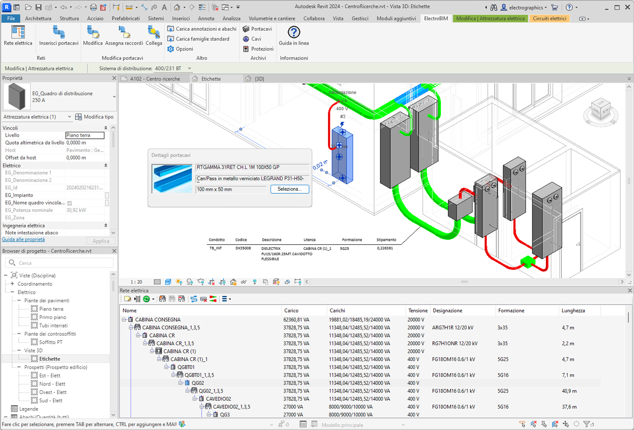
The software manages conduits and cable trays based on a library of commonly used products and associates key information to Revit routing functions, enabling 3D modeling of cable paths according to the selected product. A dedicated manager allows the definition of electrical loads, supported by a navigator that simplifies and speeds up access to typical data (voltage, power, current, power factor, cable type and installation method).
The automatic cable routing function connects the various system elements to the distribution boards and determines the optimal paths along the modeled trunks. The propagation of loads at different levels of the system determines the conductor cross-sections based on the cable types and installation methods used, correlated with the paths followed. It performs coordination with the predicted protections and calculates voltage drops at every point of the system. Finally, the filling rate of conduits is managed, whether pipes, ducts or cable trays; annotation elements are available to display all information regarding conduit occupancy.
Definition of electrical loads
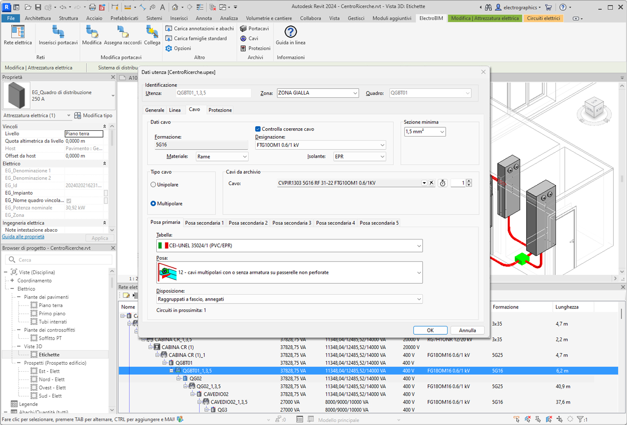
After defining the electrical equipment in Revit, the electrical network manager allows editing each element of the network, whether a load or a distribution board, assigning descriptive data and its association to an area and board. Typical data such as utilized power, power factor, electrical system, ambient temperature, number of poles and type of protection can be assigned, as well as installation tables CEI-UNEL 35024/1 - 35024/2 - 35026, IEC 364 (1983), IEC 60364-5-52, IEC 448 and IEC 61892-4. The operator may also directly assign cables and protections, selected automatically from their respective libraries containing over 100,000 items.

Equipment labeling
Labeling is provided for all electrical elements, with the ability to set the name by part type, separator characters, and an incremental index; among the properties managed in electrical equipment, the assigned label is locked, and will not be altered by automatic labeling.
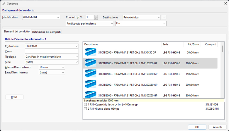
Library of conduits, cables and protections
A library with over 6,000 types of ducts or pipes is available, taken from the most common manufacturers on the market (ABB, Gewiss, Inset, Legrand); each item is defined by geometric and product parameters to uniquely drive the tracking of the 3D model in Revit for system families corresponding to the selected product type. The cable archive includes over 11,000 items, defined by technical data on the cable (construction, type, cross-sections, weights, bending radii, and conductor identification). The protection archive contains over 90,000 elements of all types, taken from leading manufacturers. All archives can be freely extended and expanded by the operator.
3D model routing
The software allows selecting the type of pipe or duct to use from the available libraries, with search criteria by manufacturer and type: it is therefore possible to accurately characterize system families used during conduit routing with Revit's standard commands. In this way, the 3D model of the distribution system becomes the real representation of the commercial product chosen for developing the electrical system's network.
Generation of the electrical power network
The electroBIM network manager retrieves all electrical information made available by the families used in the project—modeling distribution elements (panels, transformers, etc.) and terminal elements (outlets, lights, electrical devices, etc.)—following Revit’s logic for defining electrical power circuits. Simple and effective methods are offered for associating loads with circuits and connecting them to boards or power sources, directly from the network navigator. Multiple loads can be grouped and managed as a single element, simplifying network management. Each electrical parameter is linked to an Electro Graphics project parameter, visible in the Revit Properties palette.
Electrical network navigation
The electrical network navigator provides fast and productive access to all data of electrical elements, as well as quick editing with immediate localization in the Revit model. Convenient functions are available for creating circuits, assigning elements to them, or removing elements from existing circuits.
Classic network management
The working mode called Classic Network Management allows defining the electrical network independently, without relying on Revit circuits and families. Inspired by Electro Graphics’ CAD approach, this mode allows importing a network from an Ampère project and integrating it with auxiliary networks (e.g., structured cabling, fire detection, etc.). At the start of the Electrical Network command from the ribbon, a dialog asks which mode to use. Both modes rely on a .upex project file, always linked to the Revit project, and can be changed later from the Properties window. The window allows managing the networks of the system in the project. The following networks can be defined:
- Electrical network
- Auxiliary
- Structured cabling (data network)
- EVAC (emergency voice/audio evacuation systems)
- Fire alarm
- TV/SAT
Electrical network
The Networks – Electrical Network window allows opening and maintaining an electrical network generated with the Ampère electrical calculation software (optional software). Ampère provides full calculation capabilities; without it, the network management tools allow creating and solving radial electrical networks with reduced functionality. The electrical network highlights the following nodes.
Supply. Represents the starting node of the electrical network. With Ampère, multiple supplies may be defined, in which case the number of supply nodes corresponds to the number of supplies defined in the calculation software.
Panel. Distribution boards, cabinets and junction boxes, each with their identification label, are represented as intermediate nodes in the tree. The panel must be associated with one—and only one—graphical symbol in the drawing.
Riser. Represents an elevated distribution line, typically connected downstream from a panel; this element can in turn be connected to other panels or terminal loads. The riser must be associated in the drawing with a symbol representing the terminal connection of the line. This allows the software to correctly extract the total line length.
Load. The terminal load may be represented on the drawing by one or more symbols, and multiple loads may be represented by the same symbol. A function allows reading and interpreting the power value from the attributes of such symbols. It is also possible to define a set of components controlled by the same connection (e.g., switches and their lighting fixtures) by assigning the same Command attribute to all symbols.
Power propagation and protection coordination
The system propagates load power through the various levels of the installation, taking into account utilization and diversity factors defined in the network loads. Likewise, proper coordination between operating current and rated current of the protection device is calculated when present.
Automatic cable routing
Exclusion criteria can be defined to prevent specific loads from using certain conduits, as well as the opposite: force certain loads to pass through specific cable tray points. The procedure searches for the optimal path within the conduit network, considering exclusion or prioritization options, and provides:
- Accurate estimation of cable lengths.
- The number of circuits in proximity—i.e., the maximum number of cables sharing the same conduit—for correct ampacity calculations.
- Preassignment of installation method depending on whether the circuit passes through ducts, trays, or pipes.
Conductor sizing
Based on the applied standard, cable and conductor type, installation conditions, number of nearby cables, and temperature, the software determines the conductor cross-section and allows selecting the cable from the library, making available all weight and size information for correct cable tray fill calculations.
Voltage drop calculation
electroBIM computes voltage drop at every point of the network using the analytical method, considering electrical quantities in vector form; this ensures accurate evaluation of this essential design parameter.
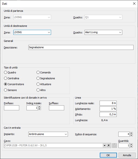
Generic auxiliary network
Auxiliary systems such as home automation can be defined similarly to the electrical network. An auxiliary network can be developed in the Networks – Auxiliary interface, defining interconnected elements and the cables linking them. All functions available for auxiliary networks follow the same logic as those for the electrical network. The software allows introducing the various units and facilitates their identification by selecting the appropriate type. Using specific linking operations, these units can be associated with components placed in the Revit model.
EVAC networks
To facilitate cable routing for emergency voice/audio evacuation systems (EVAC), the software allows introducing the components that form the terminal elements of such systems, enabling cable distribution in the designated cable trays. Current regulations require certain types of buildings to implement these systems, often in combination with standard fire detection and alarm systems. EVAC systems may also be used for non-emergency announcements and background audio. The main components of such a network are:
- Control unit. Typically a rack cabinet containing all components that generate alarm messages and monitor system functionality.
- Controller. Devices that monitor speaker lines and amplifiers, store voice messages, and distribute audio signals. Multiple controllers may be interconnected in large systems.
- Loudspeakers.
- Amplifiers. Used to amplify audio signals that must cover large areas.
- Microphone stations. Devices to input sound or alarm messages into the system.
- Router. Devices typically used to multiplex the individual stations.

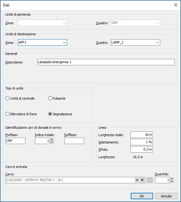
Fire alarm networks
Another auxiliary network that can be introduced is the fire alarm system. This system defines the set of electronic devices designed to detect the presence of fire inside a building, signal the alarm to occupants and responders. The definition method of network routing nodes is the same as for other auxiliary networks. Fire alarm systems can be installed in industrial buildings, multi-story structures, warehouses and commercial centers, hotels, hospitals, and public facilities. A fire alarm system typically consists of a control panel receiving signals from detection devices and issuing alarm signals through various notification devices (sirens, communication systems, etc.).
TV/SAT network
Another network type that can be defined independently in the planimetric system project is the TV/SAT network. This system defines the set of active and passive electronic devices designed for TV signal distribution in its various installation configurations. The TV/SAT network can also be developed within the Networks interface (RETI command) using the structured cabling method.
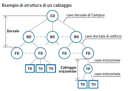
Structured cabling
Structured cabling is a design and installation method for telecommunications systems (voice and data) within buildings (LAN networks). It is therefore separate from the power distribution system (electrical network). The structure of the system is hierarchically star-shaped: it starts from a main point, reaches floor cabinets and branches out to workstations. Regardless of complexity, it can be represented by multiple levels of interconnection such as campus, building, and floor distributors, the work area with user outlets (TO), multiuser outlets (MUTO) and any consolidation points (CP).
Conduit annotations
At the end of the system design, the operator can extract cable designation and configuration and display them in the Revit model using Electro Graphics custom annotations. Annotations can be added to cable trays, showing data on loads contained in each segment and the fill factor.
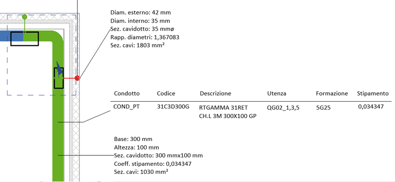
Cable tray fill checks
The network calculation also determines cable cross-sectional areas and conduit fill; this information is shown in Revit through annotative elements and with color-coded highlights in the 3D view.
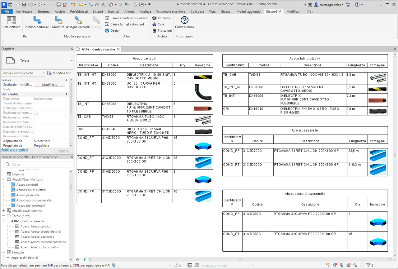
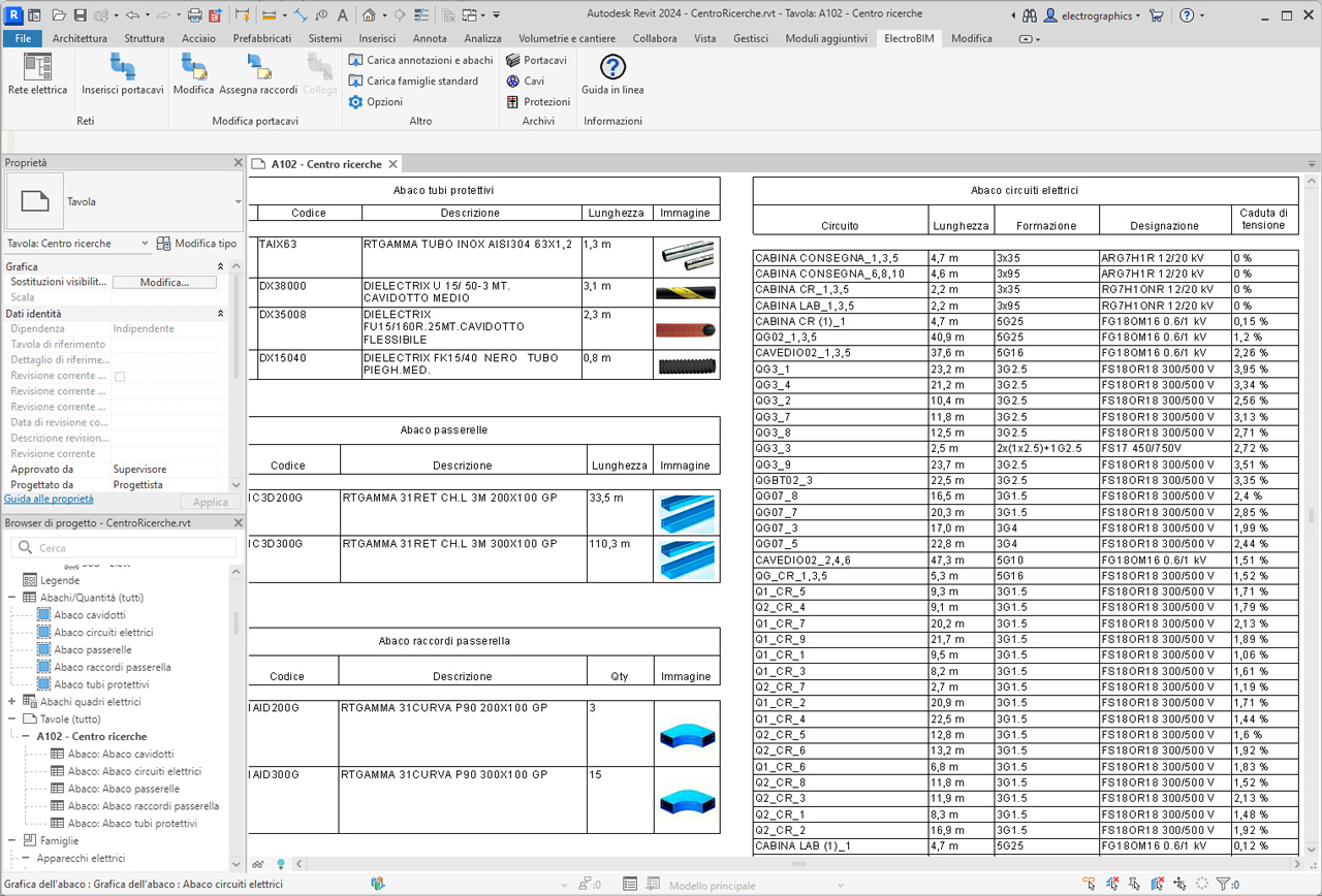
Schedules for conduits and electrical circuits
electroBIM provides a set of families for preconfigured schedules with essential electrical parameters such as voltage, power, current, all fully customizable to meet project needs. Through these schedules, it is possible to clearly display information about electrical circuits, including connected devices, load characteristics, and other relevant data. Schedules facilitate the creation of legends and technical documentation, offering a complete overview of the electrical specifications essential for proper design and maintenance of electrical systems.
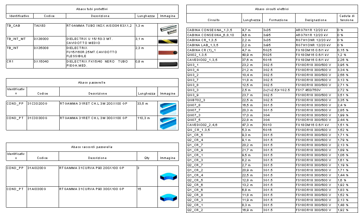
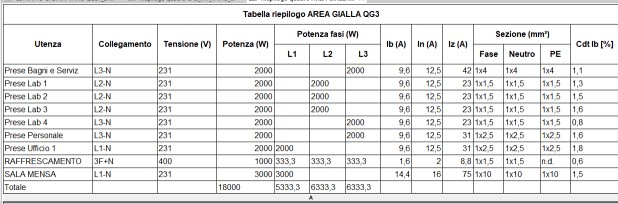
Panel summary table
This function allows creating a customized schedule for one or more electrical panels and lists all circuits powered by the panel, whether terminal circuits or feeder circuits to other panels. The command displays a dialog with the list of all available panels; the panel selected in the main window, if present, is already active in the list.
Interoperability with Ampère software
electroBIM also enables automatic data exchange between the electrical network defined in Autodesk Revit© and the Ampère line calculation software, a key feature of the BIM philosophy: information sharing to ensure easy communication and collaboration between all professionals involved in the design, construction and maintenance phases throughout the building lifecycle. The automatic data synchronization mechanism allows bidirectional linking between the Revit project and its representation in the calculation environment. electroBIM therefore allows leveraging the full power of Electro Graphics calculation tools and brings the results back into Revit according to a data exchange logic where loads and their relationships are constrained by the network defined in the BIM environment.
System requirements
Minimum system requirements to install and use electroBIM.
- Computer with 3 GHz o higher processor.
- At least 8 GB RAM.
- Hard disk with at least 10 GB free space.
- Colour video and graphics board (SVGA or higher).
- USB, mouse, printer or plotter.
- Windows 10 (version 1809 or higher) or 11.
- Autodesk© - Revit© version 2018-2024.
ElectroBIM is a plug-in for Autodesk Revit®. It is developed by Electro Graphics to support the design of electrical distribution systems in a BIM environment. After installation, ElectroBIM is loaded and accessible from the Autodesk Revit ribbon installed on the PC.
See also
The following Electro Graphics software products connect to electroBIM to complete the list of all the tools needed for a complete professional electrical engineering.


News


