
New features 2026 Series - Electrical CAD
Electro Graphics releases the latest 2026 Series of electrical and photovoltaic design software. Here are the most important features and enhancements introduced in the electric CAD CADelet, iDEA, Eplus.


See all new features 2026:
Download brochure Electro Graphics New features 2026
Eplus and iDEA are based on the new AutoCAD OEM 2025 engine
One of the main novelties of the 2026 version of iDEA and Eplus is the update from version 2025 to version 2026 of the Autodesk AutoCAD® OEM engine on which the two electrical CADs are based.
This new version of CAD offers a set of advanced features and high performance to meet the needs of the most demanding professionals.
• AutoCAD OEM 2026 CAD engine: ensures maximum accuracy, reliability and compatibility with the latest CAD file formats.
• Increased performance: top speed and responsiveness for a smooth and uninterrupted workflow.
• Advanced tools: a wide range of functionality for 2D and 3D design, analysis and technical documentation.
• Customisable user interface: an ergonomic working environment adaptable to specific needs.
CADelet supports AutoCAD 2026
• CADelet line software is now compatible with AutoCAD version 2018 to 2026 64 bit.
• Smart line software is now compatible with AutoCAD LT version 2018 to 2019 64 bit.
Optimized access to symbol libraries and material archives on a remote network, including SQL-type databases
Symbol libraries and archive databases represent crucial elements in a company's workflow, ensuring the sharing of customized blocks and updated archives. Version 2026 introduces an important innovation: the sharing of Symbol Library lists (standard and user catalogs) on a server with an SQL database, similar to what is already implemented for archives (materials, devices, cabling, ...).
Starting from version 2026, it is possible to use Microsoft SQL Server©, SQLite©, and MySQL© technologies.
Sharing on a server with an SQL database enables faster and more efficient access to symbol libraries and material archives. Work teams can collaborate more effectively on shared projects, always accessing the most up-to-date version of symbols and archives. Data centralization on an SQL database server ensures consistency and integrity of information, eliminating the risk of discrepancies between different local copies.
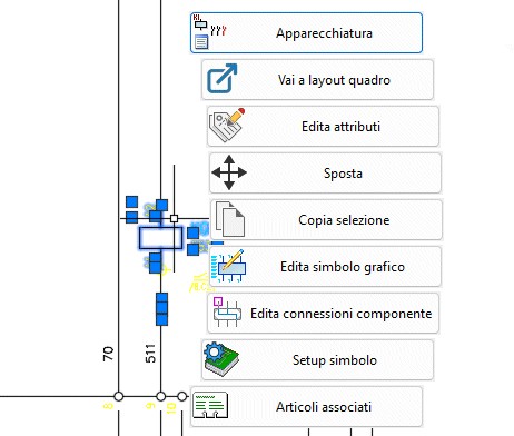
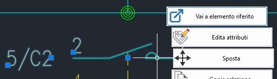
New quick contextual menu
As an alternative to the classic contextual menu of the graphical environment, it is possible to activate a new contextual menu that reacts more accurately to the context and current selection, proposing and allowing the execution of the most suitable commands based on the type of selected elements. If no elements are selected in the drawing, the menu displays commands dedicated to the project type: Wire, Terminals, Wire Analysis, etc. in a multi-sheet schematic; Network Management, Room Management, etc. in a floor-plan schematic. Based on the types and number of selected elements, the menu is populated with commands dedicated to those elements.
If the selected entity is a title block, for example, the quick contextual menu displays commands for Title Block Management, Sheet Revision, etc. If instead the symbol represents a wire, the commands related to wire and section management will be shown: Wire, Edit Connections, etc.
Localization of drawings
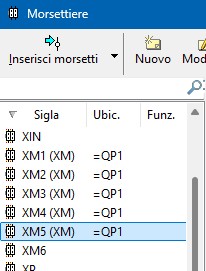
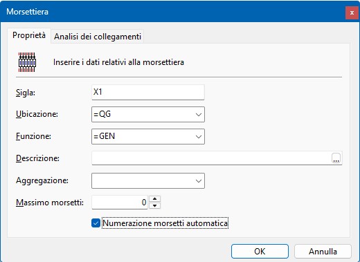
Aggregation of terminal blocks
A new property of terminal blocks allows creating aggregations of multiple terminal block groups with different identification codes in order to obtain a single representation in the electrical schematic (schematic or tabular). To define an aggregated terminal block, it is sufficient to fill in the Aggregation field with the same value in the data of all the terminal blocks that you want to assemble. In the Terminal Blocks window, it is easy to identify which elements have been aggregated because the aggregation code, if present, is shown in parentheses next to the terminal block code.
In the Terminal Block Layout and Terminal Block Table commands, the codes of the aggregated terminal blocks appear in the list, identified by specific icons that simplify their recognition.
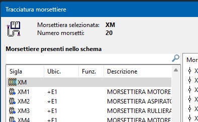
In particular, in the layout of aggregated terminal blocks, the individual terminal blocks that compose them are placed side by side, with special blocks inserted to indicate the beginning and end of each terminal block
Automatic terminal marking
The Automatic terminal numbering option enables the progressive automatic assignment of terminal pins during normal drawing operations.
Inserting, duplicating, moving, or deleting terminals belonging to a terminal block with this option enabled causes the entire terminal block to be renumbered according to the rules of the Terminal numbering command.
The sorting method can be set in the project configuration parameters, where you can choose whether to proceed with a top-down or left-right sequence. Numbering, however, is always numeric, with the first index starting from 1, and no prefixes or suffixes are provided. It is recommended to use this numbering mode for terminal blocks that reside within a single schematic drawing. In the case of disconnectable terminals, two pins will be proposed for each terminal, but if the user assigns the same pin to both sides of the terminal, this setting is preserved in subsequent renumbering operations. Any pinned values (via the Terminal pin constraint) retain the value set by the user.
Drawing of distribution bars
Distribution bars, or busbars, in an electrical panel typically connect the main power supply of the panel to the various circuits. Another example of a bar connection is the ground collector of an electrical panel, where all protective conductors (PE) converge. The Wire section dialog window now allows defining connections made through a distribution bar as “special” sections. It is possible to set one or more special sections as a distribution bar. Lines assigned to these sections are identified as bars.
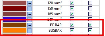
To define a special section as a bar connection, simply click on the corresponding column in the window after defining the matching line color. At this point, this type of connection can be assigned to the connections drawn in the schematic using the same operations used for assigning sections.
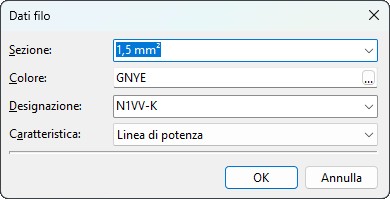
Management of the properties of the wires used in the schematic
Visual preview on the schematic 
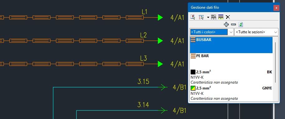
By enabling Preview during assignment, during wire data assignment operations the schematic connections take on the color corresponding to the selected conductor insulation, and the line thickness becomes proportional to the defined conductor cross-section. Dedicated line types identify connections without an assigned color or those assigned to cable connections.
This working mode helps identify, within the sheet, the connections whose wire data need modification. To activate the working mode with color and section preview, click the Enable during assignment button in the toolbar or the equivalent Enable conductor color preview during assignment option in the Assign wire data menu.
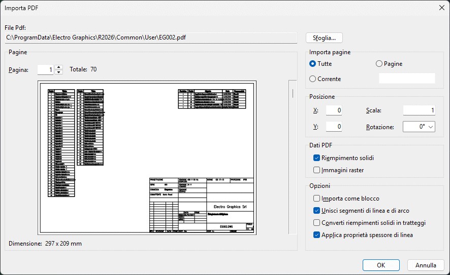
Import schematic from PDF
Grounding network
The Grounding network command (command line: TERRA) allows designing and drawing the grounding network of the electrical system, providing essential functions for defining the objects that make up the network and for arranging and interconnecting them in the system drawing/plan.
The grounding network created in the graphical environment contributes to the design of the electrical network defined in the associated load file (.upex) through Electro Graphics’ Ampère program.
Each object defined for the grounding network (collectors, earth electrodes, conductors, cables, Petersen coils) may correspond to one or more graphic objects in the drawing that share its fundamental characteristics.
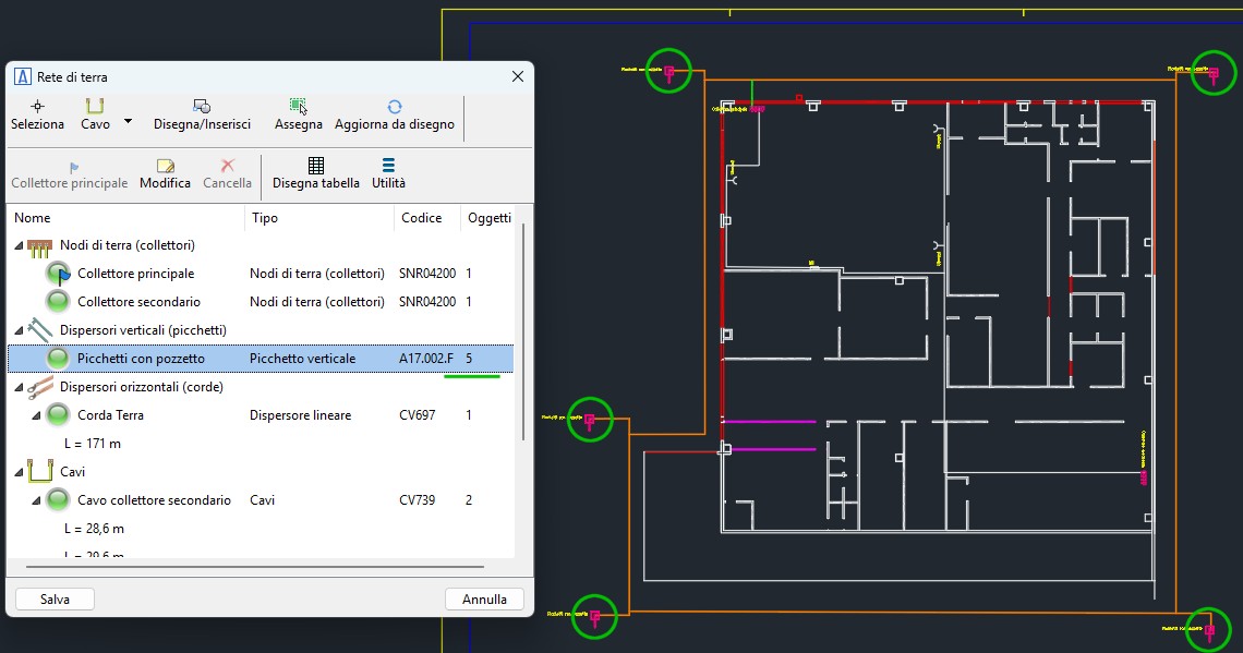

To start the grounding network drawing command, click the command icon in the ribbon, under the “Impiantistica” tab, or run TERRA from the command line.
The Grounding Network design window provides all functions needed to define the elements that make up the grounding network and to draw them.
Drawing grounding network objects
To insert a grounding network object into the drawing, select the object from the list and execute Draw/Insert from the toolbar. Alternatively, start the drawing command by dragging the selected object from the list into the drawing area.
Drawing objects of type Collector, Vertical Earth Electrode, and Petersen Coil
Objects of the Collector, Vertical Earth Electrode, and Petersen Coil types are represented in the drawing using symbols stored in the Symbol Library. When the drawing command is launched, a dialog window allows the selection of a symbol to insert among the compatible ones available in the library.
Select a symbol from the list and proceed to place it in the drawing. For Vertical Earth Electrode symbols only, the insertion operation will repeat. End or cancel the insertion using ESC.
Drawing objects of type Conductor (Linear Earth Electrode) and Cable
Objects of the Conductor (Linear Earth Electrode) and Cable types are represented graphically using polylines. It is important to make a clarification to correctly draw the grounding network:
A grounding network object—whether a symbol or another polyline associated with a conductor—is considered connected to a conductor object if it touches the polyline representing the conductor at any point along its length.
Cable objects, on the other hand, being connection elements between other grounding network objects, are considered connected only if they touch the object at the endpoints of the polyline.
When the command starts, you are asked to select the sequence of points that defines the path of the conductor or cable on the plan. End or cancel the drawing command with ESC.
Drawing conductor objects (non–linear earth electrodes)
Conductor objects of types other than Linear Earth Electrode, such as Four-point star, Rectangular mesh, etc., are inserted into the drawing through a geometric composition of polylines that conforms to the characteristics defined by the parameters of the object.
See all new features 2026:
Download brochure Electro Graphics New features 2026